Attenuation & Water Management
Attenuation & Water Management Solutions
Our attenuation water management solutions help control the rate at which water enters the watercourse or storm drain. Our industry leading patented products can be deployed in Infiltration, Permeable and Impermeable Attenuation systems, which makes their range of applications incredibly broad.
HYDROCHAMBER
The HydroChamber is an arched chamber attenuation system designed specifically for building underground storage tanks for stormwater runoff in attenuation and soak away applications.
Its superior design makes it suitable for building storage tanks under HGV trafficked and car park areas as well as non-trafficked areas (e.g. green amenity areas). JFC HydroChambers have many advantages over other similar products including BBA certification for HGV loading, superior structural strength, silt management, cost effectiveness, maintenance and inspection capabilities.
The HydroChambers are manufactured from high density polyethylene plastic and are backfilled with 35/50mm clean washed crushed stone. The corrugated arch shape of the HydroChamber provides excellent structural strength as shown in independently witnessed field tests where the chambers were exposed to loads 3.5 times greater than that expected in service.
HydroChambers can be used in three different types of stormwater management systems:
- Infiltration / Soak-away System
- Permeable Attenuation System
- Impermeable Attenuation System
A site audit will determine the most suitable system.
Features & Benefits
- BBA Certification
- Superior Structural Integrity
- Visual and Camera Inspection
- Silt/Grit Management System
- Stackable for storage on site
- Design and Installation Manuals provided
- Sizing Calculator
- AutoCAD Drawings
- Full Technical Assistance
- Installation Service
HydroChamber 800 Specification
- Overall Dimensions (mm): 2325 x 1265 x 800
- Installed Dimensions (mm): 2175 x 1265 x 800
- Nominal Storage* (m³): 2.1 – 2.8 / Chamber
- Lateral Flow: 114 Holes x Ø20mm


*System storage is dependent on foundation depth, distribution pipe diameter and the overall system size.
See HydroChamber calculator for more details.
Inspection & Maintenance
The HydroChamber is a unique attenuation system that minimizes the entrance of grit / silt due to the two upstream catch-pit manholes. Standard drain cleaning and inspection equipment allows maintenance and inspection to be conducted on the main distribution pipe. Chamber rows can be camera inspected as required.


Make JFC your Stormwater Management Consultant and Provider
Inspection & Maintenance
- Customised stormwater management solutions in accordance with local authority legislation
- Tank sizing and calculations
- Detailed report (for planning permission)
- On site consultation
Supply and Installation Services
JFC offer a number of options when supplying and installing a stormwater management system
- Supply and install
- Supply and supervise
- Supply only
All JFC Stormwater management solutions include full excavation drawings
JFC also offer a number of services to enhance the supply and installation of the stormwater management system.
These include:
- Full Design Service
- Stormwater Management Reports
- Excavation Drawings
- AutoCAD Drawings
- Excel Calculators
- Design Manuals
- Installation Manuals
- BBA Certification
- Technical Presentations
- Local Authority Support
*System storage is dependent on foundation depth, distribution pipe diameter and the overall system size. See HydroChamber calculator for more details.
OriChamber
Single Dwelling Orifice Control Chamber
The JFC OriChamber is a prefabricated unit which comprises a twinwall chamber with base. 110mm internal and outlet pipework and a pedestrian duty (bolt down) cover. The unit is available in two standard depths of 1.0m and 1.5m incorporating a 150mm sump. (other depths available to order).
Features & Benefits:
- Prefabricated for ease of installation
- Removable cover and frame to allow shaft to be trimmed on-site to suit final levels.
- Two inlet seals supplied along with a hole-saw to allow them to be located at a suitable level and orientation.
- Overflow pipe which can be removed to allow the system to be drained if the orifice becomes blocked.
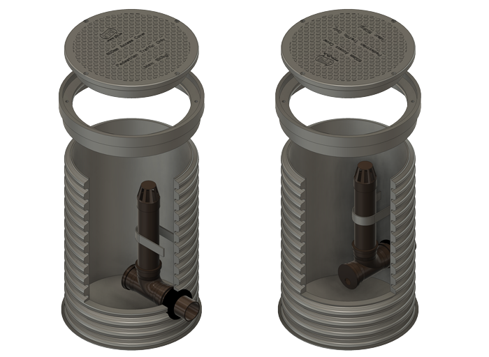
Fitted with a 110mm overflow pipe complete with debris cowl, the pipe and cowl can be removed if the orifice becomes blocked which allows the system to drain down and the blockage removed.
Two number 110mm inlet connection seals are supplied loose with a hole saw enabling them to be fitted easily to the required level and orientation on-site. This offers unique flexibility to the user.


The internal pipework is assembled from 110mm pipework and has an end cap which can be drilled with a certain diameter hole, based on the design flow and design head required (see table below). For specific head and flows contact JFC Civils Technical Team.

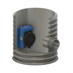
HYDROSEAL
The HydroSeal is a rotationally moulded flanged coupler designed to create a watertight seal when JFC CorriPipe™ passes through an impermeable liner (or GCL layer) commonly found in stormwater attenuation systems. The unit comprises two identical flanged couplers one of which has a pre-fabricated internal neoprene layer.
It is very easy to install. One half is placed either side of where the pipe is to pass through the impermeable membrane or GCL layer. When bolted back to back the impermeable layer becomes sandwiched between the units creating a tight seal. The impermeable layer is then trimmed away from the inside of the joint and a standard twinwall CorriPipe™ can be attached
Features & Benefits:
- Quick and easy to install
- Tight seal
- No on-site welding required
- Available in several sizes
- Can be installed in wet weather
Product Gallery


INTERCEPTORS
Surface water drains normally discharge to a watercourse or indirectly into underground waters via a soak away. Contamination of surface water by oil, chemicals or suspended solids can cause these discharges to have a serious impact on the receiving water. Interceptors protect receiving waters from such pollutants.
Operation:
Interceptors remove pollutants from effluent and allow cleaner water to pass into a surface water drainage system. Pollutants are retained for removal and disposal. Interceptors work by allowing the pollutants and water to naturally separate. Pollutants float to the surface of the water for easy removal. Silt settles within the unit and can be easily removed. All JFC Interceptors are manufactured to IS EN ISO; 9001:2000 and conform to European Standard PR EN 858 – 1 & 2.
ByPass Interceptor
- Used on low risk sites (Car Parks)
- Sized in litres per second flow
- Available in Class 1 format

Sizes:
| Product Code | Drainage Area m² | Peak Flow (L/s) | Nominal Flow (L/s) | Oil Storage (L) | NSB Ref |
|---|---|---|---|---|---|
| BPDA1950 | 1,950 | 3.5 | 35 l | 52.5 | 3.5 |
| BPDA2500 | 2,500 | 4.5 | 45 | 67.5 | 4.5 |
| BPDA3300 | 3,300 | 6.0 | 60 | 90 | 6 |
| BPDA4400 | 4,400 | 8.0 | 80 | 120 | 8 |
| BPDA5555 | 5,555 | 10.0 | 100 | 150 | 10 |
| BPDA6900 | 6,900 | 12.5 | 125 | 187.5 | 12.5 |
| BPDA8300 | 8,300 | 15 | 150 | 225 | 15 |
| BPDA10000 | 10,000 | 18 | 180 | 270 | 18 |
| BPDA13333 | 13,333 | 24 | 240 | 360 | 24 |
Best Management Practice:
Best management practices should be maintained to ensure a clean network at all times. Sinkable solids and floatable contaminants should be prevented where possible from entering the unit by means of a dedicated silt trap(s) and/or sumped catchpit manhole (s) upstream thus preventing potential problems.
It is important to note that a large amount of the settable solids are present in the network during construction and this is mainly due to the silt/grit present in construction runoff. To account for this, the following inspection and maintenance guidelines are recommended:
- Initially inspect the catchpit manholes on a monthly basis (periodically thereafter)
- If cathchpit is 30% full, de-sludge the catchpit (s) with a standard vacuum tanker
- If large amounts of silt present, additional catchpit manholes with 90 degree bends may be required
- When construction is finished a full camera inspection is recommended on the network
- Any contaminants found in the line should be flushed/jetted and the catchpits de-sludged
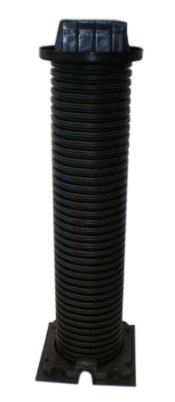
STOP TAP CHAMBER
The stop tap chamber is installed to provide a quick and efficient method of accessing below ground stop taps on a mains water line.
A surface level lid allows a tool be inserted into the circular shaft connecting with the stop valve. This tool is rotated to open or close the stop valve which will turn on or off the mains water supply.
| Product Code | Description |
|---|---|
| STC | Stop Tap Chamber |
The Stop Tap Chamber consists of four parts:
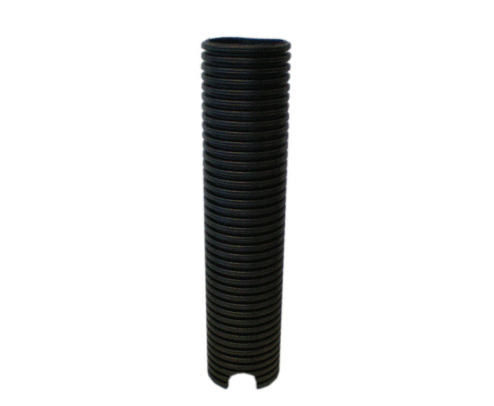
- The shaft is made from CorriPipe™ (150mmØ) and is 0.75m in length. There are two arches at the bottom of the shaft which allow the pipe to fit tightly into the base.
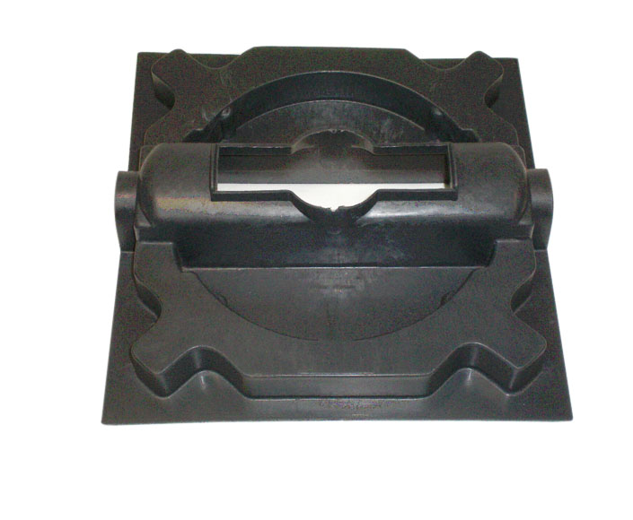
- The Top Hat is fitted over the top of the pipe shaft and is designed so the surface box will lock into place.
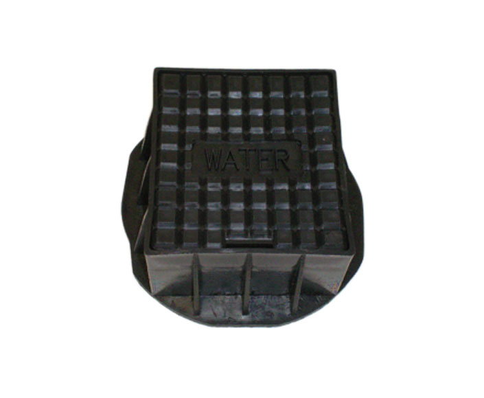
- The Surface box is hinged and load rested to grade C as specified in BS5834 PT2 1983 (Dimensions: 125 x 100 x 75 (mm)
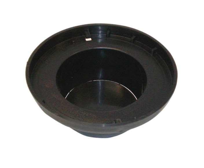
- The base is designed to fit over the stop valve and will accept 150mm twinwall pipe.
- The Base, Top Hat and Surface Box are manufactured from recycled polypropylene.
| Product Code | Description |
|---|---|
| 1TST/TH | Circular Sleeve / Top Hat |
| 94/056/W | Surface Box |
| 1TST/B | Base |
| 1TST 0.75 | 0.75 CorriPipe Length |
Product Gallery
CONTACT A MEMBER OF OUR SALES TEAM TODAY
Click here ask us a question, or request a call back to discuss your requirements today!

Pipe &
Ducting

Water Management

Fat, Oil & Grease Management

Storage
Tanks

Traffic Management